Hydrogen 1
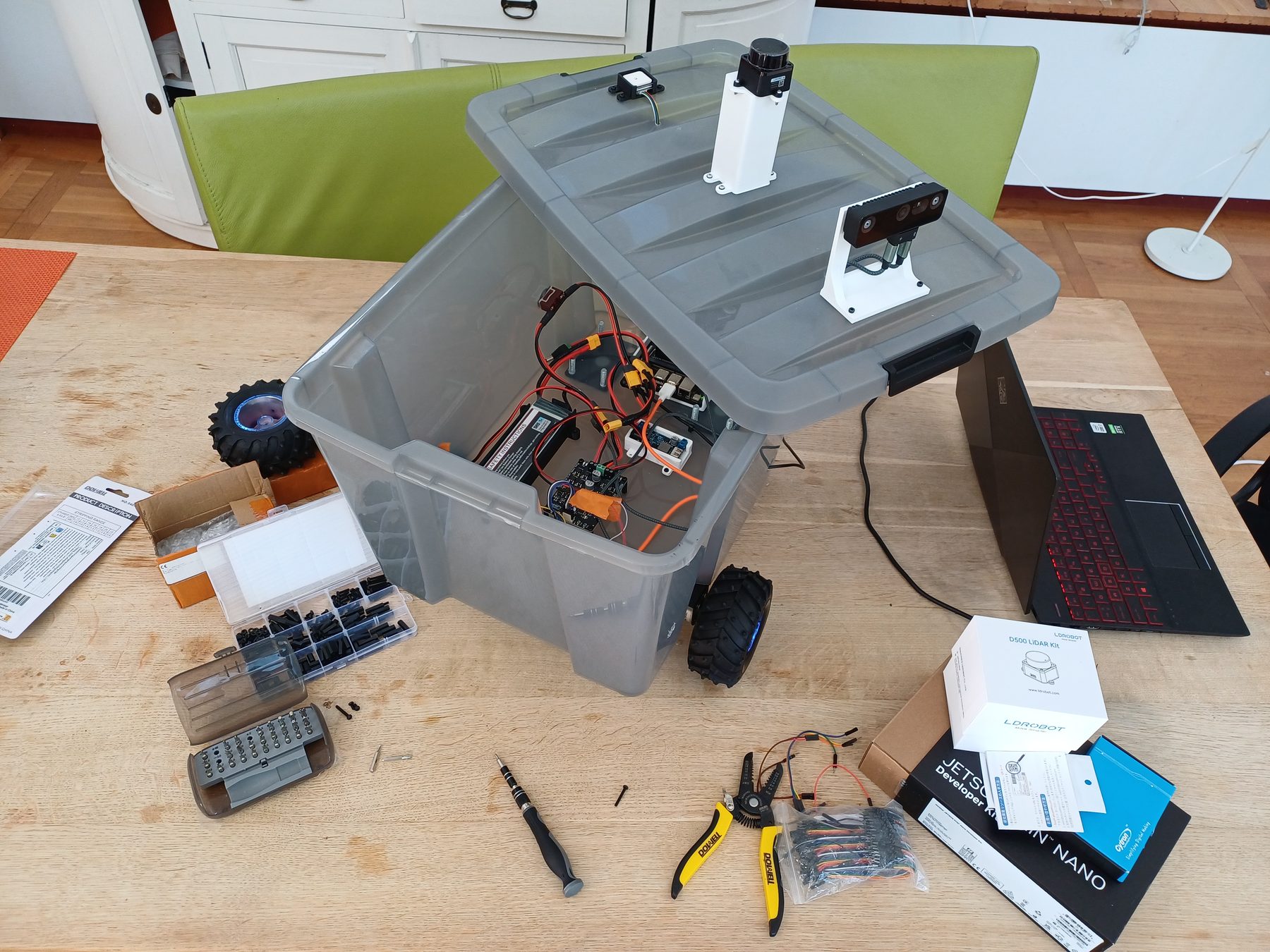
A 24″ × 16″ inches differential drive robot I am designing and building from scratch to navigate from A to B on a map, mostly on sidewalks. Building the whole system myself: autonomy, perception, mechatronics and the safety measures around them.
- Footprint
- 24″ × 16″, differential drive
- Compute
- Jetson Orin Nano Super + RP2040
- Sensing
- GNSS, IMU, wheel encoders, 2D LiDAR, stereo depth
- Navigation
- Nav2, MPPI controller, layered costmap
- Perception
- PIDNet-S and YOLO26n, TensorRT INT8
- Simulation
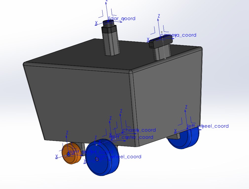
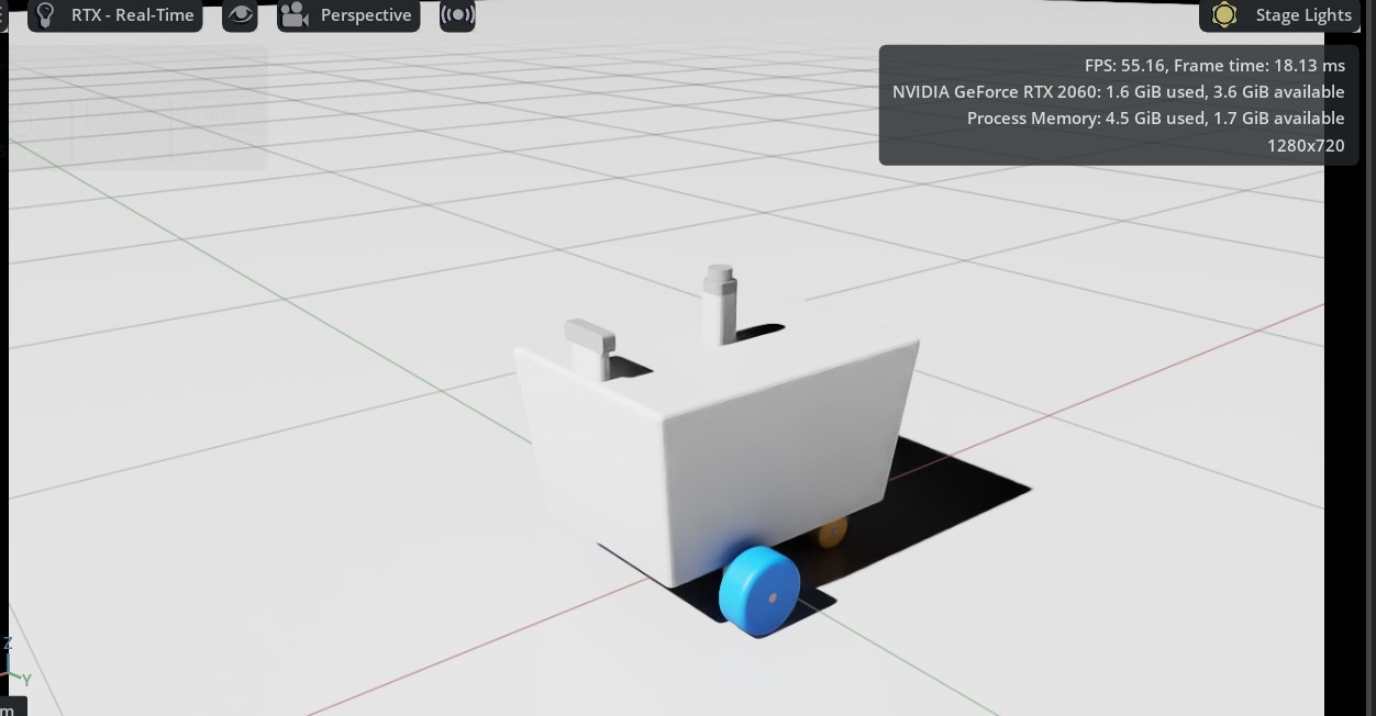
- SolidWorks to URDF, Gazebo and Isaac Sim
A sidewalk is not a warehouse
Indoor robots get a clean map, flat floors and a known set of obstacles. A sidewalk gives you none of that: parked scooters and bins change the geometry daily, the surface is cambered and broken, people move unpredictably, and GNSS degrades sometimes too.
Hydrogen 1 is my attempt to learn as much of that problem as I can by building the whole thing: take a delivery task expressed as two points on a map, and work out what it really takes to make a physical machine carry it out on real pavement, from choosing the motors to sizing the power bus to writing the stack.
Two brains, one bus
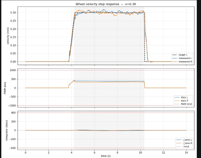
Everything that has to think runs on the Jetson. Everything that has to be on time runs on the Pico. That split means a slow inference frame can never stall a wheel loop, and the microcontroller never has to know what a costmap is.
The two talk over micro-ROS on a USB serial link, so the firmware is a first-class ROS 2 node rather than a custom protocol to keep in sync.
Knowing where it is
Nav2 needs two things from localisation that conflict. The local controller needs a pose that is continuous, or a GNSS fix arriving looks like a huge instantaneous velocity and the robot lurches. The planner needs a pose that is globally correct, or the robot follows a perfectly smooth path to the wrong street.
robot_localization,
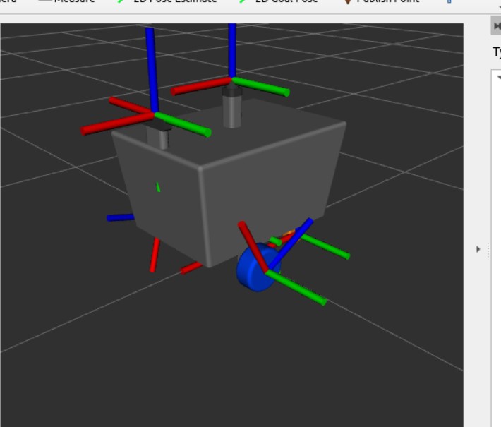
and the TF tree they produce.scroll to panSo there are two. The first fuses only the continuous sources, IMU and wheel odometry,
and publishes odom to base_link: it drifts, but it never jumps,
and the MPPI controller runs against it. The second also takes the GNSS position,
transformed out of WGS84 by navsat_transform_node, and publishes the
correction as map to odom.
Drift correction lands in that transform instead of inside the pose the controller is differentiating, so the robot can lose satellites for a stretch, keep driving on dead reckoning, and never feel the discontinuity when the fix returns.
One grid, five opinions
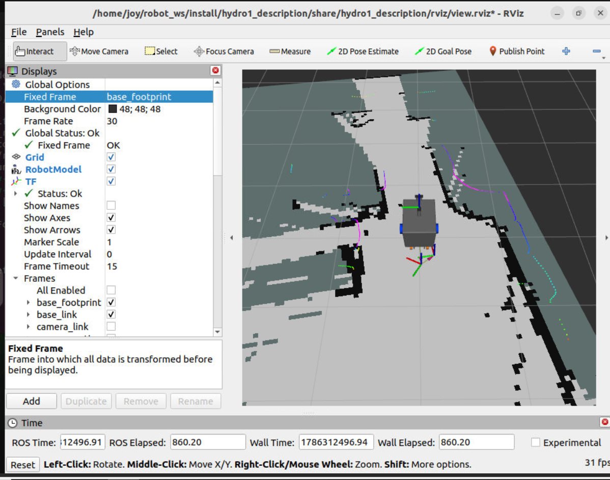
A 2D LiDAR is honest about geometry and blind to meaning: it cannot tell a kerb from a step, or pavement from road. A camera is the opposite. Both run, plus stereo depth, and each writes into the same rolling grid as a costmap layer. The controller never talks to a sensor, it talks to the grid.
It optimises over a horizon rather than a single step, so it commits to going around an obstacle early instead of noticing it late and stopping. And because the cost is a weighted sum of critics, the behaviour is tunable in terms an engineer can reason about: clearance, path deviation, and how much to punish jerky angular velocity, which matters on a differential drive base where a sharp rotational command scrubs the tyres.
Built, then validated twice
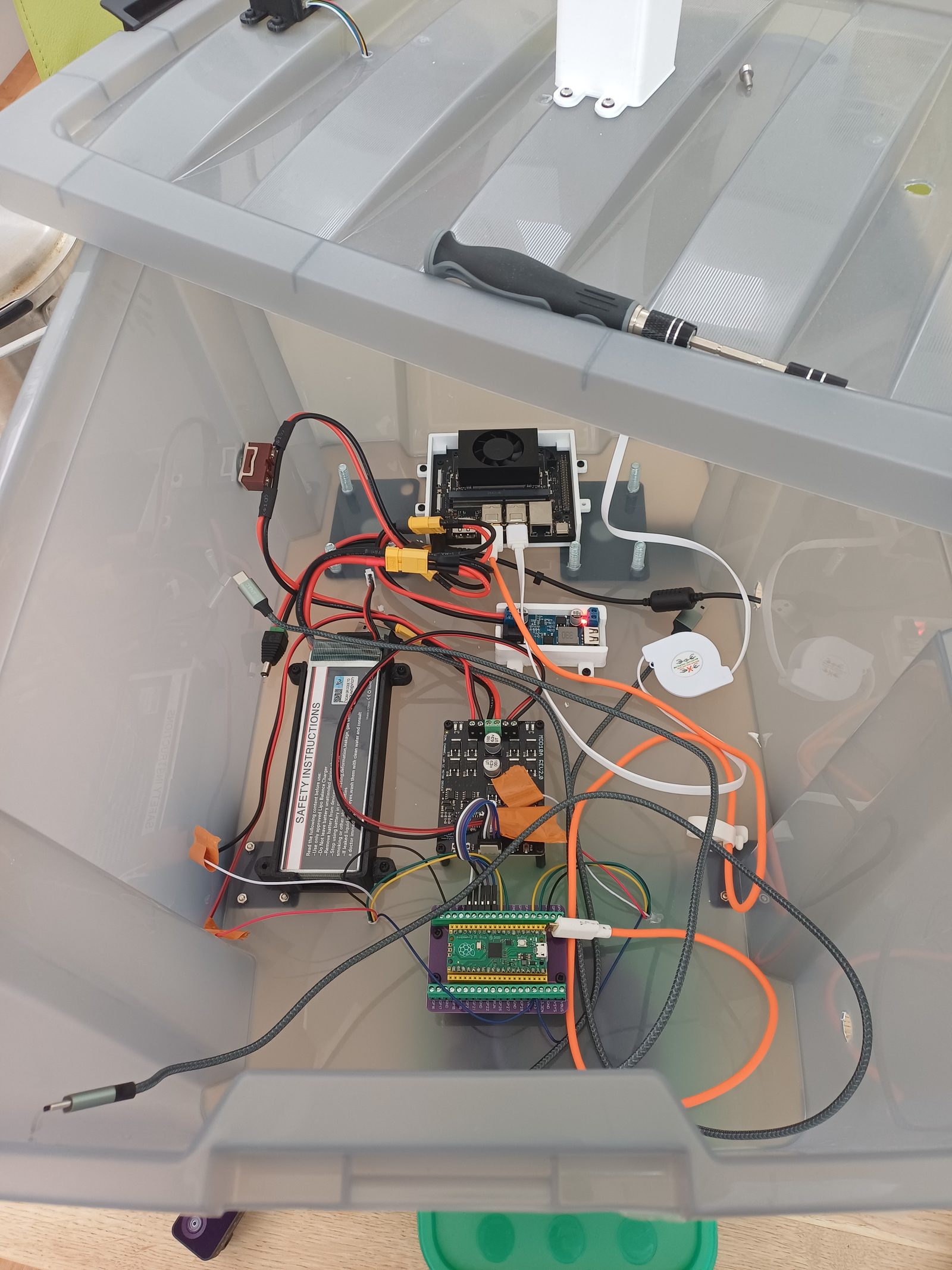
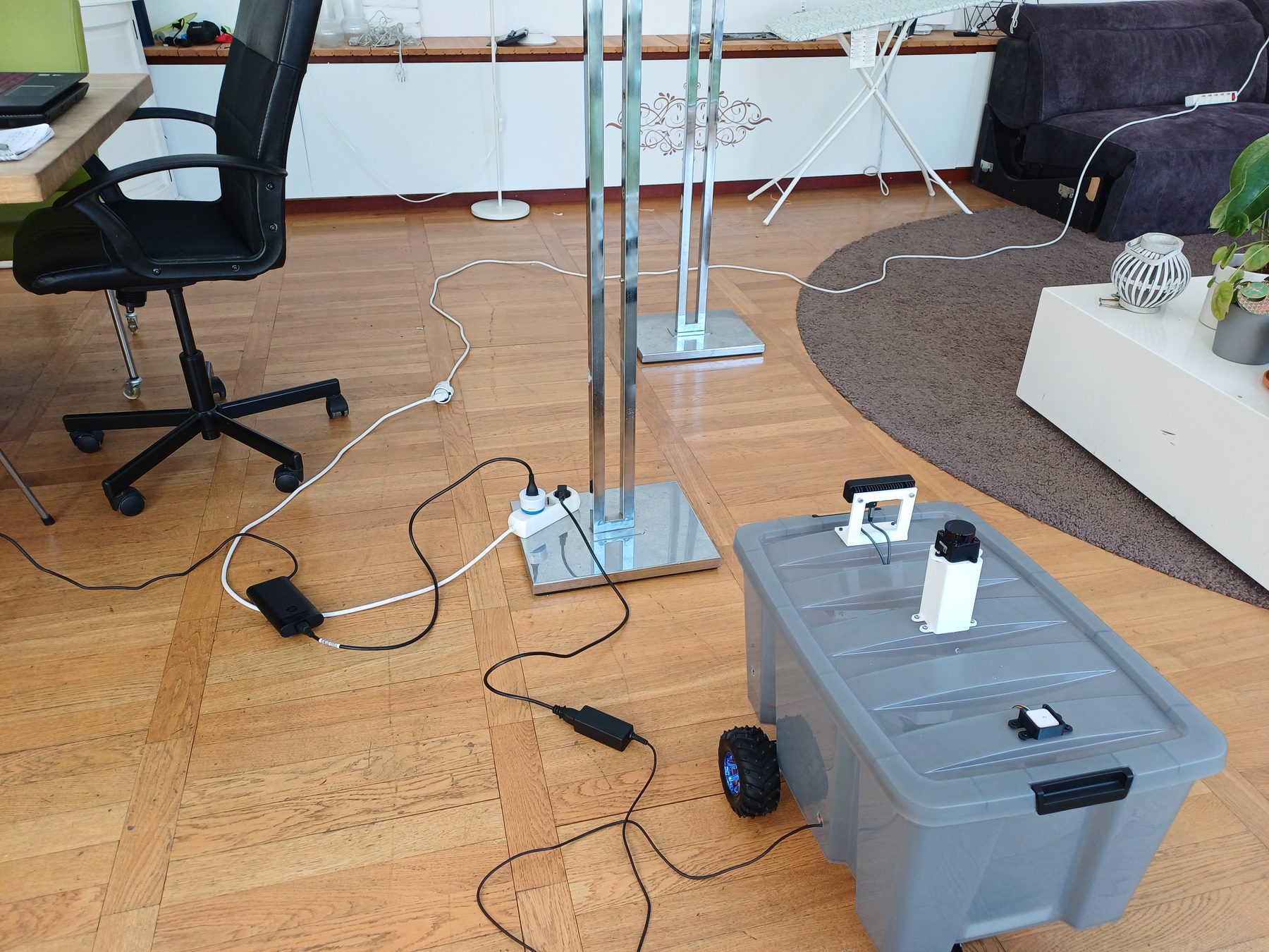
The body is a sealed polypropylene crate: weather resistant, a lid that opens the whole top, and a flat floor that takes a mounting plate without fabrication. Everything structural around it is 3D printed.
Two DC gearmotors driven by a Cytron MDD10A dual channel driver, a Luxonis OAK-D Pro for stereo RGB and depth, and a BE880 GNSS module on the mast.
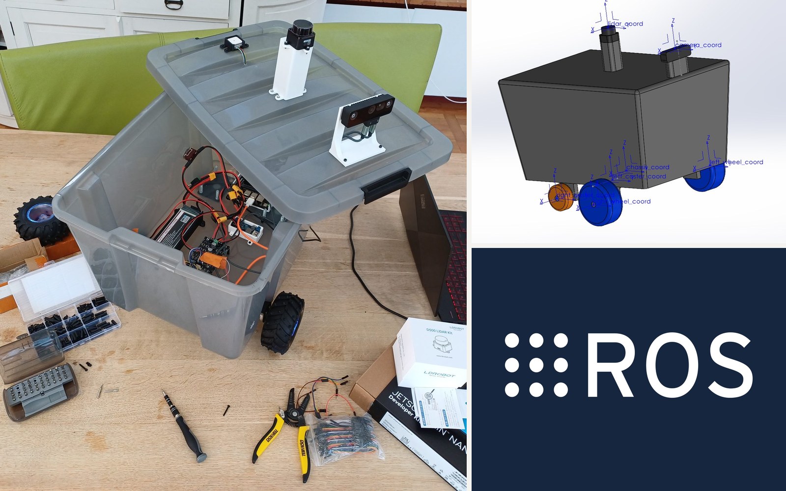
The same geometry was drawn in SolidWorks, exported to URDF with real link frames and inertias, checked in RViz, then driven in Gazebo and Isaac Sim, so the stack can be exercised against a robot a bad gain cannot break.