Five challenges
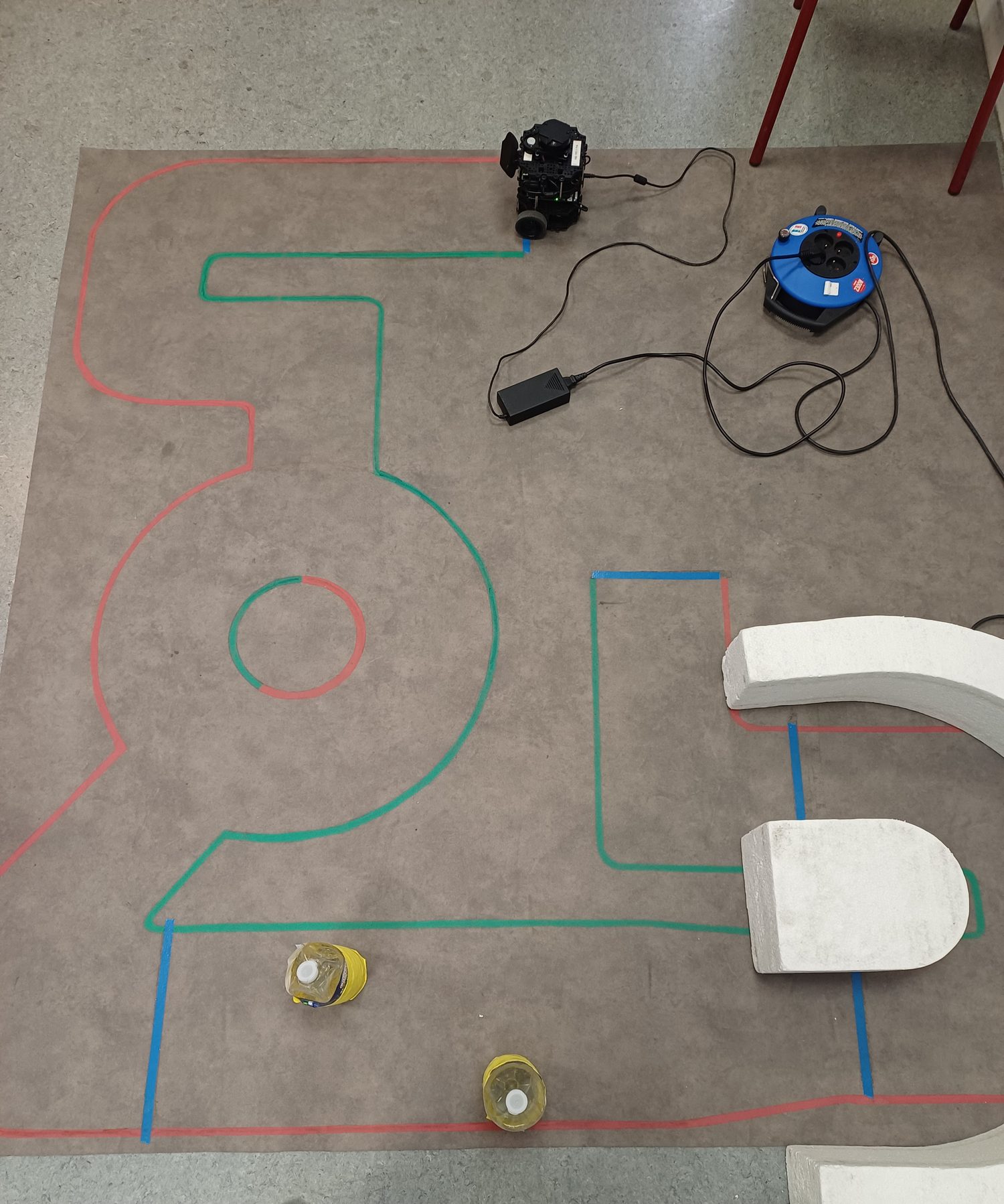
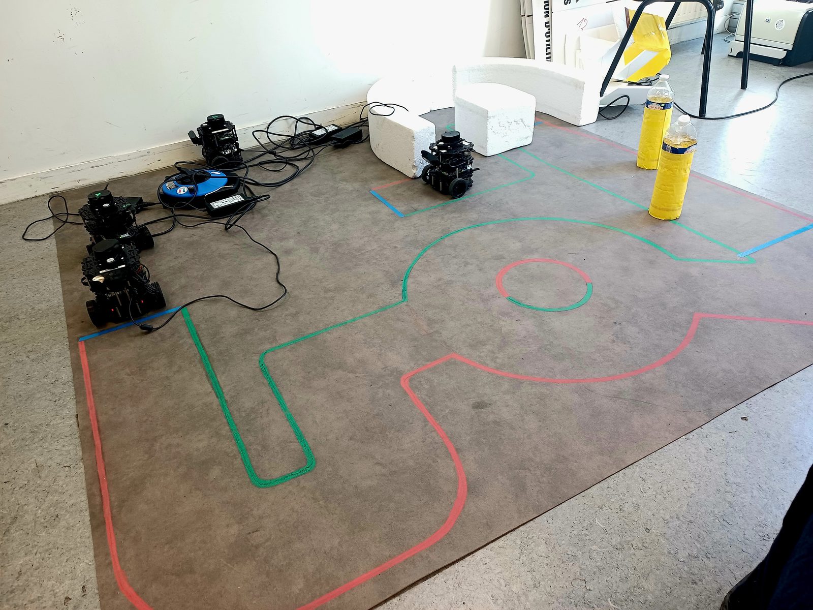
One TurtleBot 3 Burger, one taped indoor course, and five autonomy problems that had to be solved in a single continuous run: follow the lane, take the roundabout, get around a static obstacle, thread a tight corridor, and score a ball into a goal.
- Platform
- TurtleBot 3 Burger, Raspberry Pi and OpenCR
- Sensing
- Monocular camera, 360° LDS-01 scanner
- Perception
- OpenCV, HSV masks, polynomial lane fitting
- Control
- Proportional-derivative steering on lane error
- Arbitration
- Finite state machine with a failsafe state
- Simulation
- Gazebo replica of the physical course
Five problems, one robot
The five behaviours use different sensors and different control laws, but only one control algorithm at a time. Lane following runs on the camera, obstacle avoidance and corridor on the LiDAR, and the ball scoring needs both at once. Most of the work went into optimizing each challenge's behaviour, then combining them into one sequence.
-
Lane following
Fit the green line on the left and the red one on the right, and steer on the error between the lane centre and the image centre.
-
Roundabout navigation
Commit to an arc and leave on the correct exit, instead of orbiting forever.
-
Static obstacle avoidance
See the 2 blocks on the LiDAR scanner and calculate the optimal route to avoid them.
-
Tight corridor
No tape at all, so control switches to keeping the left and right ranges balanced.
-
Ball scoring
Get behind the ball on the line it has to travel along, then push.
From pixels to a turn rate
The pipeline is deliberately classical: colour thresholds, image moments and a second order fit. No network, no training set, no GPU, which keeps the per-frame cost low enough for the Raspberry Pi to run the loop at camera rate.
HSV separates hue from brightness, which is what makes tape on a shiny floor tractable: a specular highlight changes value dramatically and hue barely at all. The image is cut into horizontal bands, image moments give one centroid per band per colour, and those points are fitted with a second order polynomial. A straight line cannot represent the entry to a curve; anything higher starts chasing noise.
One of the two lines is often missing, in a roundabout or where tape has lifted, so the follower reports which colours it has and changes geometry to match: with both it steers to the midpoint, with one it holds a fixed offset on the correct side.
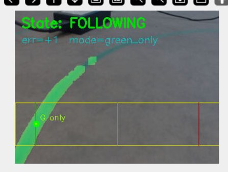
mode=green_only. The red line has run
out, so the robot holds an offset from green.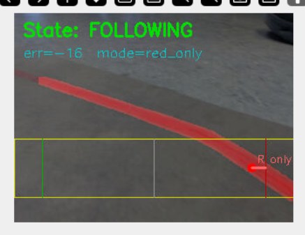
mode=red_only, err = -16. The mirror
case, on the other side of the lane.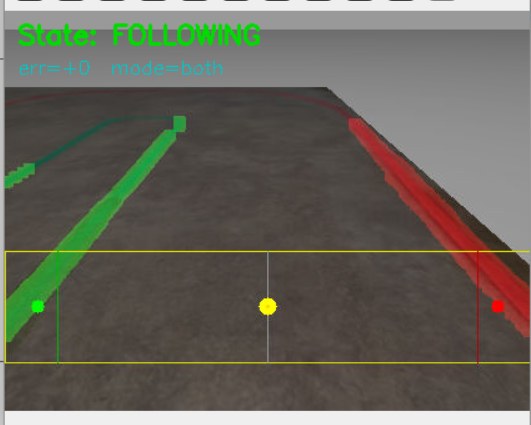
mode=both. The yellow box is the
sampling band, the dots are the per-band centroids.Every frame carries its own state, mode, error, heading and fit degree burned into the image. When something goes wrong on the course you do not reason about it, you scroll back and read what the robot believed at that instant.
One state at a time
Five behaviours wanting the same wheels is a recipe for a robot that shakes in place. A finite state machine solves that the boring way: exactly one behaviour owns the velocity command, and transitions are explicit guards evaluated on every camera callback.
Two details carry most of the robustness. Every specialised state has a way
home, so a mis-detection costs a few seconds rather than the run, and transitions
are debounced, because one frame that happens to see an arc is not a roundabout. The
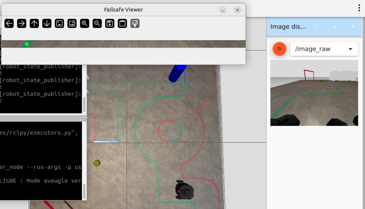
FAILSAFE state exists because this runs in a room with people in it: an
operator stop pulls the machine out of whatever it is doing immediately.
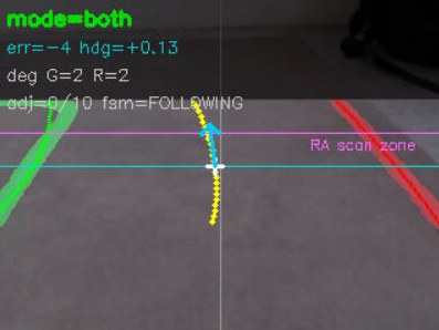
err=-4 hdg=+0.13, fit degree 2 on both colours, the debounce counter, and
the scan zone the obstacle guard watches.Sectors, then geometry
The LDS-01 gives a full 360° ring of ranges. The guard reduces the ring to a handful of sector minima, and both obstacle avoidance and corridor following are written against those few numbers rather than an array of 360 floats.
When the front sector closes below its gate the robot leaves the lane, goes around while the side sector still sees the obstacle, and rejoins only once the lane detector reports a usable line again, so the manoeuvre never counts wheel turns and hopes. In the corridor it simply steers on the difference between the left and right minima.
Scoring is a small geometry problem. The ball's horizontal centre gives its bearing and
its apparent diameter gives the range; from the goal's own bearing the state computes
the aim error, which is the angle between where the robot is approaching from and the
line the ball has to travel along. Then it waits, because the stable
counter has to hold for several frames before it commits, and there is no second chance
once the ball has moved.
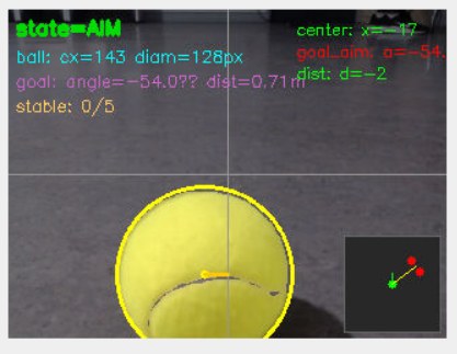
state=AIM. Ball at
cx=143, diam=128px; goal bearing and range on the right;
stable: 0/5 counting up to the commit.Gazebo Simulation
A Gazebo replica, same tape colours, same roundabout, same corridor walls, same ball, meant the state machine could be debugged for hours before touching the physical robot.
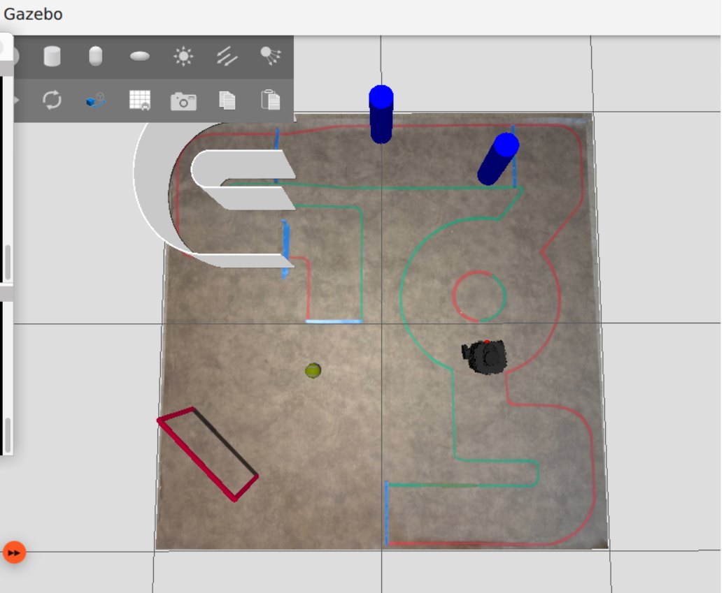
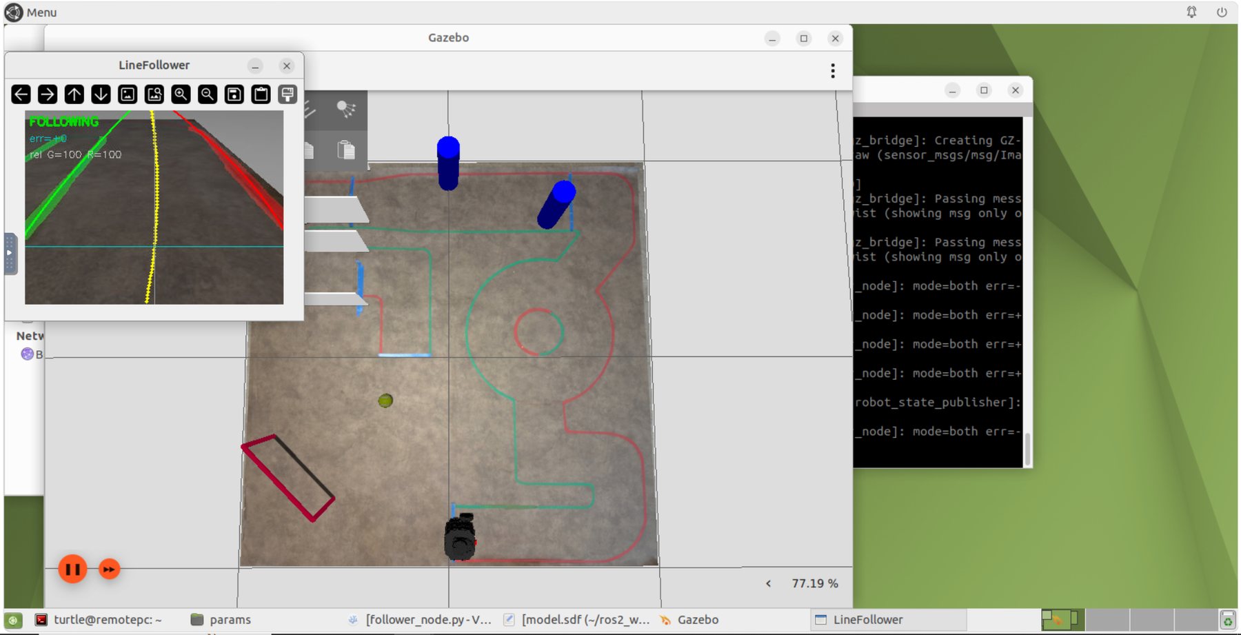
Structure transferred cleanly: state transitions, debounce counts, the geometry of the aim, every recovery path. Colour did not, because simulated tape under simulated light is not real tape under fluorescent tubes, so every HSV range had to be retuned on the physical course. Logic in simulation, thresholds on hardware, is the lesson I took into the sidewalk robot.